Recently, Cui Yongjie, a young teacher of our institute, published a research paper titled Impactof Electrostatic Interaction on Vertical Morphology and Energy Loss inEfficient Pseudo-Planar Heterojunction Organic Solar Cells as the co-first author in the top international materials journal Advanced Materials (SCI Zone 1 TOP, IF=29.4) online. Impactof Electrostatic Interaction on Vertical Morphology and Energy Loss inEfficient Pseudo-Planar Heterojunction Organic Solar Cells. In addition, the recent collaborative work of young teacher Cui Yongjie has been published in the international journals AngewandteChemie International Edition (DOI: 10.1002/anie.202400086 and DOI: 10.1002/anie.202318595), Nanoenergy (DOI: 10.1016/j. 10.1016/j.nanoen.2023.109218), Nanoenergy (DOI: 10.1016/j.nanoen.2023.109218), and ChemPhotoChem (DOI:10.1002/cptc.202300256) have been published.

brief description
Organic solar cells (OSCs) have received extensive research attention due to their light weight, solution processing and large area production. The body heterojunction structure (BHJ) is a commonly used device structure with a bicontinuous nano-interpenetrating network structure. Due to the random mixing of donor (D) and acceptor (A) materials in solution at a certain ratio, it is difficult for the BHJ to form a suitable vertical phase separation (VPS) morphology, which hampers the enhancement of device performance. In order to optimize the VPS morphology of the active layer, a quasi-planar heterojunction structure (PHJ) with the donor enriched at the anode and the acceptor enriched at the cathode has been prepared by using a continuous spin-coating method of D and A. However, the most efficient OSCs are currently prepared using chloroform as a solvent for film deposition, and when A deposition is performed on D, the strong swelling effect of chloroform leads to a large amount of D-A mixing, which is not conducive to the formation of excellent VPS morphology. In addition, the formation of VPS topography in PHJ structures is a complex process, and the formation mechanism is still unclear.

Figure 1.(a) Molecular structure and molecular electrostatic potential. (b) Contact angles on water and diiodomethane. (c) Summary of surface energy and χ data. (d) Schematic representation of the formation of the active layer of the PHJ structure under different ∆ESP.
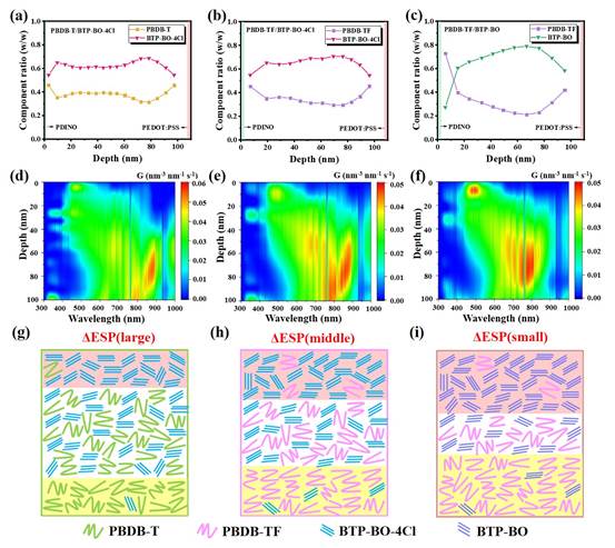
Fig. 2.(a-c) Membrane thickness-dependent component distribution curves. (d-f) Calculated contour plots of exciton generation along the membrane thickness. (g-i) Schematic representation of the film morphology for different ∆ESPs (pink shaded parts represent acceptor enrichment and yellow shaded parts represent donor enrichment).
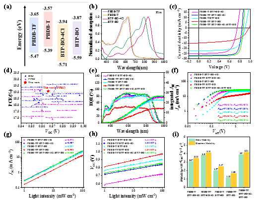
Figure 3.(a) Energy level diagram; (b) UV-vis absorption spectra in pure film. (c) J-V curve. (d) Brief summary of PCE vs. VOC for BHJ and PHJOSCs based on the BTP-BO-4Cl family of receptors in this and previous papers. (e) EQE spectra, (f) Jph-Veff curves, (g) JSC-light intensity, (h) VOC-light intensity curves and (i) carrier mobility.
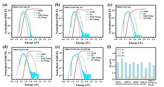
Fig. 4.(a-e) Normalized s-EQE and EL data for different devices. (f) Histogram of device energy loss.
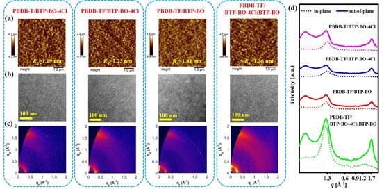
Fig. 5.(a) AFM image, (b) TEM image and (c) GIWAXS image. (d) Corresponding intensity distributions along the out-of-plane (solid line) and in-plane (dashed line) directions.
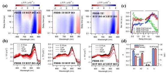
Fig. 6.(a) TA curves and (b) spectral probes (delay 0.15, 1, 10, 100 ps). (c) Comparison of hole transfer kinetics of blended films. (d) Parameters of hole transfer process in binary and ternary blended films.
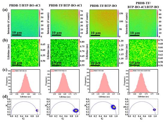
Figure 7. time-resolved confocal imaging (780 nm excitation). (a) photoluminescence, (b) lifetime imaging, (c) histogram of lifetime distribution and (d) phase volume diagram.
